of similar units proceeds from starboard to port,
forward to aft, and from a lower to a higher level.
Within a given compartment, then, the numbering
of similar units follows the same rule; that is, LOWER
takes precedence over UPPER, FORWARD over
AFT, and STARBOARD over PORT.
Electrical distribution panels, control panels, and
so forth, are given identification numbers made up of
three numbers separated by hyphens. The first number
identifies the vertical level by deck or platform
number at which the unit is normally accessible.
Decks of Navy ships are numbered by using the main
deck as the starting point as described in Basic
Military Requirements, NAVEDTRA 12043. The
numeral 1 is used for the main deck, and each
successive deck above is numbered 01, 02, 03, and so
on, and each successive deck below the main deck is
numbered 2, 3, 4, and so on.
The second number identifies the longitudinal
location of the unit by frame number. The third
number identifies the transverse location by the
assignment of consecutive odd numbers for centerline
and starboard locations and consecutive even numbers
for port locations. The numeral 1 identifies the lowest
centerline (or centermost, starboard) component.
Consecutive odd numbers are assigned components as
they would be observed first as being above, and then
outboard, of the preceding component. Consecutive
even numbers similarly identify components on the
portside. For example, a distribution panel with the
identification number, 1-142-2, will be located on the
main deck at frame 142, and will be the first
distribution panel on the port side of the centerline at
this frame on the main deck.
Main switchboards or switchgear groups supplied
directly from ship’s service generators are designated
1S, 2S, and so on. Switchboards supplied directly by
emergency generators are designated 1E, 2E, and so
on. Switchboards for special frequencies (other than
the frequency of the ship’s service system) have ac
generators designated 1SF, 2SF, and so on.
Sections of a switchgear group other than the
generator section are designated by an additional
suffix letter starting with the letter A and proceeding
in alphabetical order from left to right (viewing the
front of the switchgear group). Some large ships are
equipped with a system of distribution called zone
control. In a zone control system, the ship is divided
into areas generally coinciding with the fire zones
prescribed by the ship’s damage control plan.
Electrical power is distributed within each zone from
load center switchboards located within the zone.
Load center switchboards and miscellaneous
switchboards on ships with zone control distribution
are given identification numbers, the first digit of
which indicates the zone and the second digit the
number of the switchboard within the zone as
determined by the general rules for numbering
electrical units discussed previously.
Cable Marking
Metal tags embossed with the cable designations
are used to identify all permanently installed
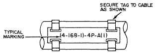
shipboard electrical cables. These tags (fig. 6-1) are
placed on cables as close as practical to each point of
connection on both sides of decks, bulkheads, and
other barriers. They identify the cables for
maintenance and replacement. Navy ships use two
systems of cable marking; the old system on pre-1949
ships, and the new system on those built since 1949.
We will explain both systems in the following
paragraphs.
OLD CABLE TAG SYSTEM.—In the old
system, the color of the tag shows the cable
classification: red—vital, yellow—semivital, and
gray or no color—nonvital. The tags will contain the
following basic letters that designate power and
lighting cables for the different services:
C
D
F
FB
G
MS
P
R
RL
S
Interior communications
Degaussing
Ship’s service lighting and general power
Battle power
Fire control
Minesweeping
Electric propulsion
Radio and radar
Running, anchor, and signal lights
Sonar
FE
Emergency lighting and power
Figure 6-1.—Cable tag.
6-2


