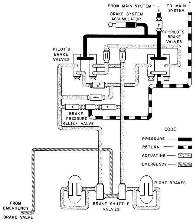
Figure 5-17 shows that the lines on the hydraulic
diagram are identified as to purpose and the arrows
point the direction of flow. Figure 5-18 and appendix
II contain additional symbols and conventions used
on aircraft hydraulic and pneumatic systems and in
fluid power diagrams.
PLUMBING PRINTS
Plumbing prints use many of the standard piping
symbols shown in figure 5-9. MIL-STD-17B Parts I
and II lists other symbols that are used only in
plumbing prints, some of which are shown in figure
5-19.
Figure 5-17.—Aircraft power brake control valve system.
5-13