CHAPTER 4
MACHINE DRAWING
When you have read and understood this chapter,
you should be able to answer the following learning
objectives:
Describe basic machine drawings.
Describe the types of machine threads.
Describe gear and helical spring nomenclature.
Explain the use of finish marks on drawings.
This chapter discusses the common terms, tools,
and conventions used in the production of machine
drawings.
COMMON TERMS AND SYMBOLS
In learning to read machine drawings, you must first
become familiar with the common terms, symbols, and
conventions defined and discussed in the following
paragraphs.
GENERAL TERMS
The following paragraphs cover the common terms
most used in all aspects of machine drawings.
Tolerances
Engineers realize that absolute accuracy is
impossible, so they figure how much variation is
permissible. This allowance is known as tolerance. It
is stated on a drawing as (plus or minus) a certain
amount, either by a fraction or decimal. Limits are the
maximum and/or minimum values prescribed for a
specific dimension, while tolerance represents the total
amount by which a specific dimension may vary.
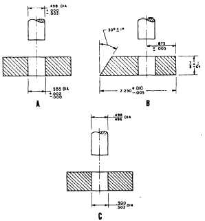
Tolerances may be shown on drawings by several
different methods; figure 4-1 shows three examples.
The unilateral method (view A) is used when variation
from the design size is permissible in one direction only.
In the bilateral method (view B), the dimension figure
shows the plus or minus variation that is acceptable. In
the limit dimensioning method (view C), the maximum
and minimum measurements are both stated
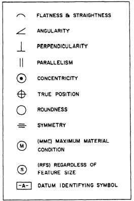
The surfaces being toleranced have geometrical
characteristics such as roundness, or perpendicularity to
another surface. Figure 4-2 shows typical geometrical
characteristic symbols. A datum is a surface, line, or
Figure 4-1.—Methods of indicating tolerance.
Figure 4-2.—Geometric characteristic symbols.
4-1