often drawn to a larger scale than the view of the object
from which it is removed.
BROKEN-OUT SECTION.—The inner struc-
ture of a small area may be shown by peeling back or
removing the outside surface. The inside of a
Figure 3-22.—Broken-out section through a counterbored
Exploded View
hole.
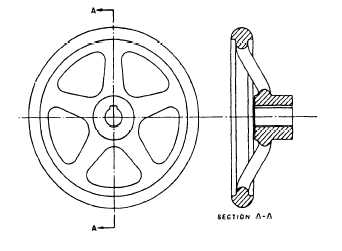
Figure 3-23.—Aligned section.
counterbored hole is better illustrated in figure 3-22
because of the broken-out section, which makes it
possible for you to look inside.
ALIGNED SECTION.—Figure 3-23 shows an
aligned section. Look at the cutting-plane line AA on
the front view of the handwheel. When a true
sectional view might be misleading, parts such as ribs
or spokes are drawn as if they are rotated into or out
of the cutting plane. Notice that the spokes in section
A-A are not sectioned. If they were, the first
impression might be that the wheel had a solid web
rather than spokes.
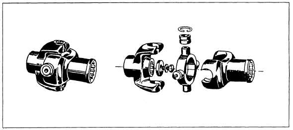
This is another type of view that is helpful and
easy to read. The exploded view (fig. 3-24) is used to
show the relative location of parts, and it is
particularly helpful when you must assemble complex
objects. Notice how parts are spaced out in line to
show clearly each part’s relationship to the other
parts.
DETAIL DRAWINGS
A detail drawing is a print that shows a single
component or part. It includes a complete and exact
description of the part’s shape and dimensions, and
how it is made. A complete detail drawing will show
in a direct and simple manner the shape, exact size,
type of material, finish for each part, tolerance,
necessary shop operations, number of parts required,
and so forth. A detail drawing is not the same as a
Figure 3-24.—An exploded view.
3-8


