The cables between the various units are tagged
showing the circuit or system designation and the num-
ber as stated earlier. In addition, the interconnection
diagram also shows the type of cable used. For example,
look at cable R-ES11 between the power supply unit
and the modulator unit in figure 6-18. R-ES11 identifies
the cable as the number 11 cable of a surface search
radar system. The MSCA-19 (16 ACT) is the designa-
tion for a multiconductor ship control armored cable
with 19 conductors, 16 active and 3 spares.
Individual conductors connecting to terminal
boards are tagged with a vinyl sleeving called spaghetti
that shows the terminal board and terminal to which the
outer end of the conductor is connected. For example,
the ends of the conductor in cable R-ES11 connected to
terminals F423 on ITB2 and 2TB2 would be tagged as
shown in figure 6-19.
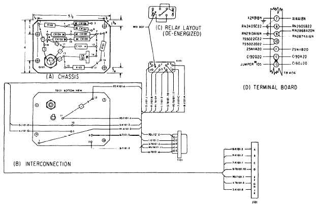
AIRCRAFT ELECTRONICS PRINTS
Aircraft electronics prints include isometric wiring
diagrams of the electronics systems showing the loca-
tions of the units of the systems and the interconnecting
wiring. Both simplified and detailed block and sche-
matic diagrams are used. They show operation and
Figure 6-19.—Conductor markings.
Figure 6-20.—Aircraft wiring diagram.
6-20


