is applied to the pin 3 grid of V603, and so on. In
addition, the schematic diagram in figure 6-13 shows
that the north reference burst signal is fed through 22K
(22,000 ohms) resistor R604 grid 7 and that the plate
output of V601B is coupled through capacitor C605 (a
330 picofared capacitor) to the grid of section A of
V602, twin-triode type 12AT7 tube. Therefore, the
detailed schematic diagram shows detailed information
about circuits and parts and must be used in conjunction
with the detailed block diagram to effectively trou-
bleshoot a system.
Wiring Diagrams
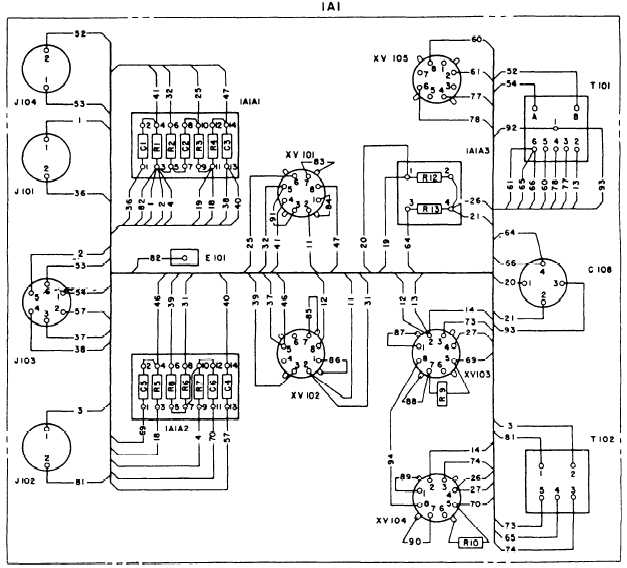
Electronic equipment wiring diagrams show
the relative positions of all equipment parts and
all electrical connections. All terminals, wires, tube
they appear in the actual equipment. Figure 6-14 shows
a sample wiring diagram. Designations 1A1, 1A1A1,
and 1A1A2 are reference designations and will be dis-
cussed later.
Figure 6-15 shows the basic wiring color code for
electronic equipment.
Reference Designations
A reference designation is a combination of letters
and numbers used to identify the various parts and
components on electronic drawings, diagrams, parts
lists, and so on. The prints you work with will have
one of two systems of reference designations. The old
one is called a block numbering system and is no
longer in use. The current one is called a unit
numbering system. We will discuss both in the
sockets, resistors, capacitors, and so on are shown as
following paragraphs.
Figure 6-14.—Sample wiring diagram.
6-16


