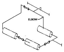
Draftsmen use single-line drawings to show the
arrangement of pipes and fittings. Figure 5-3 is a
single-line (isometric) pictorial drawing of figure 5-1.
The center line of the pipe is drawn as a thick line to
which the valve symbols are added.
Single-line drawings take less time and show all
information required to lay out and produce a piping
system.
Double-line pipe drawings (fig. 5-4) require more
time to draw and therefore are not recommended for
production drawings. Figure 5-4 is an example of a
Figure 5-3.—Single-line pictorial piping drawing of figure 5-1.
double-line pictorial pipe drawing. They are generally
used for catalogs and similar applications where visual
appearance is more important than drawing time.
CROSSINGS
The crossing of pipes without connections is
normally shown without interrupting the line
representing the hidden line (fig. 5-5, view A). But
when there is a need to show that one pipe must pass
behind another, the line representing the pipe farthest
from the viewer will be shown with a break, or
interruption, where the other pipe passes in front of it,
as shown in figure 5-5, view B.
CONNECTIONS
Permanent connections, whether made by welding
or other processes such as gluing or soldering, should
be shown on the drawing by a heavy dot (fig. 5-6). The
draftsman normally will use a general note or
specification to describe the type of connection.
Detachable connections are shown by a single
thick line (figs. 5-6 and 5-7). The specification, a
general note, or bill of material will list the types of
connections such as flanges, unions, or couplings and
whether the fittings are flanged or threaded.
Figure 5-4.—Double-line pictorial piping drawing.
5-2


