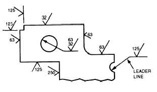
which it refers. If space is limited, the symbol may be
placed on an extension line on that surface or on the tail
of a leader with an arrow touching that surface as shown
in figure 4-18.
When a part is to be finished to the same roughness
all over, a note on the drawing will include the direction
“finish all over” along the finish mark and the proper
number. An example is FINISH ALL OVER32. When
a part is to be finished all over but a few surfaces vary
in roughness, the surface roughness symbol number or
numbers are applied to the lines representing these
surfaces and a note on the drawing will include the
surface roughness symbol for the rest of the surfaces.
For example, ALL OVER EXCEPT AS NOTED (fig.
4-19).
Figure 4-18.—Methods of placing surface roughness symbols.
STANDARDS
American industry has adopted a new standard,
Geometrical Dimensioning and Tolerancing, ANSI
Y14.5M-1982. This standard is used in all blueprint
production whether the print is drawn by a human hand
or by computer-aided drawing (CAD) equipment. It
standardizes the production of prints from the simplist
hand-made job on site to single or multiple-run items
produced in a machine shop with computer-aided
manufacturing (CAM) which we explained in chapter
2. DOD is now adopting this standard For further
information, refer to ANSI Y14.5M-1982 and to
Introduction to Geometrical Dimensioning and
Tolerancing, Lowell W. Foster, National Tooling and
Machining Association, Fort Washington, MD, 1986.
The following military standards contain most of
the information on symbols, conventions, tolerances,
and abbreviations used in shop or working drawings:
ANSI Y14.5M-1982
Dimensioning and Tolerancing
MIL-STD-9A
Screw Thread Conventions and
Methods of Specifying
ANSI 46.1
MIL-STD-12,C
Surface Texture
Abbreviations for Use On Drawings
and In Technical-Type Publications
FIgure 4-19.—Typical examples of symbol use.
4-7


