and results in severe bending that stresses the beam,
which must be resisted by both the beam and the weld.
Welding symbols are a means of placing complete
information on drawings. The top of figure 7-3 shows
the welding symbol with the weld arrow. The arrow
serves as a base on which all basic and supplementary
symbol information is placed in standard locations. The
assembled welding symbol is made up of weld symbols
in their respective positions on the reference line and
arrow, together with dimensions and other data (fig.
7-3).
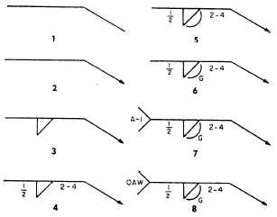
Look at figures 7-3 and 7-4 to help you read the eight
elements of a welding symbol. Each element is
numbered and illustrated separately in figure 7-4, and
explained in the following paragraphs:
1. This shows the reference line, or base, for the
other symbols.
3. This shows the basic weld symbols. In this case
it should be a fillet weld located on the arrow
side of the object to be welded.
2. This shows the arrow. The arrow points to the
4. This shows the dimensions and other data. The
location of the weld.
1/2 means the weld should be 1/2 inch thick, and
Figure 7-4.—Elements of a welding symbol.
Figure 7-3.—Standard location of elements and types of welding symbols.
7-5


