An ELLIPSE is a plane curve generated by a point
moving so that the sum of the distance from any point
on the curve to two fixed points, called foci, is a
constant (fig. 2-12). Ellipses represent holes on
oblique and inclined surfaces.
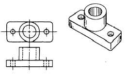
CIRCLES on drawings most often represent holes
or a circular part of an object.
An IRREGULAR CURVE is an unlike circular
arc where the radius of curvature is not constant. This
curve is usually made with a French curve (fig. 2-6).
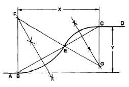
An OGEE, or reverse curve, connects two parallel
lines or planes of position (fig. 2-13).
BASIC COMPUTER AIDED DRAFTING
(CAD)
The process of preparing engineering drawings on
a computer is known as computer-aided drafting
(CAD), and it is the most significant development to
occur recently in this field. It has revolutionized the
way we prepare drawings.
The drafting part of a project is often a bottleneck
because it takes so much time. Drafter’s spend
approximately two-thirds of their time “laying lead.”
Figure 2-12.—Example of an ellipse.
Figure 2-13.—A reverse (ogee) curve connecting two parallel
planes.
But on CAD, you can make design changes faster,
resulting in a quicker turn-around time.
CAD also can relieve you from many tedious
chores such as redrawing. Once you have made a
drawing you can store it on a disk. You may then call
it up at any time and change it quickly and easily.
It may not be practical to handle all of the drafting
workload on a CAD system. While you can do most
design and drafting work more quickly on CAD, you
still need to use traditional methods for others. For
example, you can design certain electronics and
construction projects more quickly on a drafting table.
A CAD system by itself cannot create; it is only
an additional and more efficient tool. You must use
the system to make the drawing; therefore, you must
have a good background in design and drafting.
In manual drawing, you must have the skill to
draw lines and letters and use equipment such as
drafting tables and machines, and drawing aids such
as compasses, protractors, triangles, parallel edges,
scales, and templates. In CAD, however, you don’t
need those items. A cathode-ray tube, a central
processing unit, a digitizer, and a plotter replace them.
Figure 2-14 shows some of these items at a computer
work station. We’ll explain each of them later in this
section.
GENERATING DRAWINGS ON CAD
A CAD computer contains a drafting program that
is a set of detailed instructions for the computer. When
you bring up the program, the screen displays each
function or instruction you must follow to make a
drawing.
The CAD programs available to you contain all of
the symbols used in mechanical, electrical, or
architectural drawing. You will use the keyboard
and/or mouse to call up the drafting symbols you need
as you need them. Examples are characters, grid
patterns, and types of lines. When you get the symbols
you want on the screen, you will order the computer
to size, rotate, enlarge, or reduce them, and position
them on the screen to produce the image you want.
You probably will then order the computer to print the
final product and store it for later use.
The computer also serves as a filing system for any
drawing symbols or completed drawings stored in its
memory or on disks. You can call up this information
any time and copy it or revise it to produce a different
symbol or drawing.
2-8


