Views
Introduction
When drawing or projecting images on paper, you select a surface on the
object and draw that surface parallel to the picture plane or paper surface.
This creates a drawing with a limited amount of descriptive information.
Technical drawings or blueprints must show a great deal more information
and show it accurately. This often requires you to draw the same object as if
you were looking from different viewpoints, bisecting piece parts, or
exploding objects of complex design.
Views
A view is an image that results when an observer looks perpendicularly
toward one face of an object and obtains a true view of the size and shape of
that side. This one view provides only two of the three principal dimensions
(width, height, and depth) of an object. You find the third dimension in an
adjacent view. Some objects requiring only single view drawings to describe
them are shafts, bolts, washers, and other similar items. More often than
not, objects require two or multiple views to fully describe its features.
Multiview
projection
Multiview projection is a systematically arranged set of views providing
certain definite information about an object. You can view any object from
six mutually perpendicular directions either by shifting the object with
respect to the observer or by shifting the observer with respect to the object.
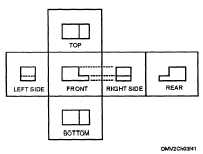
The American National Standard arrangement of views vertically aligns the
top, front, and bottom views and horizontally aligns the rear, left-side, front,
and right-side views. Drawing a view out of place is a serious error, which
can lead to confusion and wasted production hours.
Figure 3-41 shows the American National Standard for view arrangement.
Figure 3-41.—View
arrangement.
Continued on next page
3-46


