projection. The rear plane is hinged to the right side
plane, but it could hinge to either of the side planes or
to the top or bottom plane. View B shows that the
projections on the sides of the box are the views you
will see by looking straight at the object through each
side. Most drawings will be shown in three views, but
occasionally you will see two-view drawings,
particularly those of cylindrical objects.
A three-view orthographic projection drawing
shows the front, top, and right sides of an object. Refer
to figure 3-7, view C, and note the position of each of
the six sides. If you eliminate the rear, bottom, and left
sides, the drawing becomes a conventional 3-view
drawing showing only the front, top, and right sides.
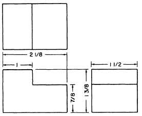
Study the arrangement of the three-view drawing
in figure 3-8. The views are always in the positions
shown. The front view is always the starting point and
the other two views are projected from it. You may use
any view as your front view as long as you place it in
the lower-left position in the three-view. This front
view was selected because it shows the most
characteristic feature of the object, the notch.
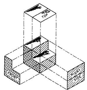
Figure 3-9.—Pull off the views.
The right side or end view is always projected to
the right of the front view. Note that all horizontal
outlines of the front view are extended horizontally to
make up the side view. The top view is always
projected directly above the front view and the vertical
outlines of the front view are extended vertically to the
top view.
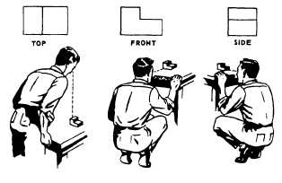
After you study each view of the object, you can
see it as it is shown in the center of figure 3-9. To
clarify the three-view drawing further, think of the
object as immovable (fig. 3-10), and visualize yourself
moving around it. This will help you relate the
blueprint views to the physical appearance of the
object.
Figure 3-8.—A three-view orthographic projection.
Figure 3-10.—Compare the orthographic views with the
model.
Now study the three-view drawing shown in
figure 3-11. It is similar to that shown in figure 3-8
with one exception; the object in figure 3-11 has a hole
drilled in its notched portion. The hole is visible in the
top view, but not in the front and side views.
Therefore, hidden (dotted) lines are used in the front
and side views to show the exact location of the walls
of the hole.
The three-view drawing shown in figure 3-11
introduces two symbols that are not shown in figure
3-8 but are described in chapter 2. They are a hidden
line that shows lines you normally can’t see on the
object, and a center line that gives the location of the
exact center of the drilled hole. The shape and size of
the object are the same.
3-4


