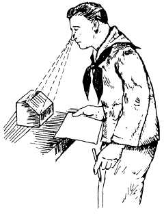
with figure 3-15 together with the other information. It
should clearly explain the reading of the auxiliary view.
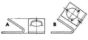
Figure 3-16 shows a side by side comparison of ortho-
graphic and auxiliary views. View A shows a fore-
shortened orthographic view of an inclined or slanted
surface whose true size and shape are unclear. View B
uses an auxiliary projection to show the true size and
shape.
The projection of the auxiliary view is made by the
observer moving around an immovable object, and the
views are projected perpendicular to the lines of sight.
Remember, the object has not been moved; only the
position of the viewer has changed.
Section Views
Section views give a clearer view of the interior or
hidden features of an object that you normally cannot
see clearly in other views. A section view is made by
visually cutting away a part of an object to show the
shape and construction at the cutting plane.
Figure 3-15.—Viewing an inclined surface, auxiliary view.
Figure 3-16.—Comparison of orthographic and auxiliary
projections.
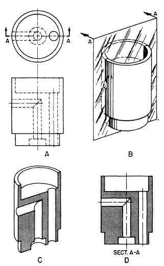
Notice the cutting plane line AA in the front view
shown in figure 3-17, view A. It shows where the
imaginary cut has been made. In view B, the isometric
view helps you visualize the cutting plane. The arrows
point in the direction in which you are to look at the
sectional view.
View C is another front view showing how the
object would look if it were cut in half.
In view D, the orthographic section view of section
A-A is placed on the drawing instead of the confusing
front view in view A. Notice how much easier it is to
read and understand.
When sectional views are drawn, the part that is
cut by the cutting plane is marked with diagonal (or
crosshatched), parallel section lines. When two or more
parts are shown in one view, each part is sectioned or
crosshatched with a different slant. Section views are
necessary for a clear understanding of complicated
parts. On simple drawings, a section view may serve the
purpose of additional views.
Figure 3-17.—Action of a cutting plane.
3-6


