Auxiliary Views
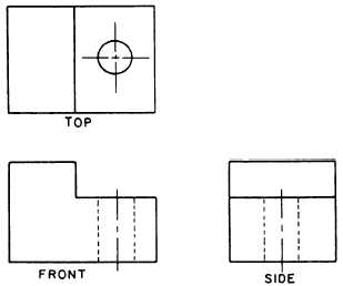
Figure 3-11.—A three-view drawing.
PERSPECTIVE DRAWINGS
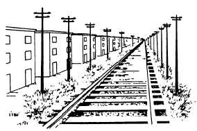
A perspective drawing is the most used method of
presentation used in technical illustrations in the
commercial and architectural fields. The drawn
objects appear proportionately smaller with distance,
as they do when you look at the real object (fig. 3-12).
It is difficult to draw, and since the drawings are drawn
in diminishing proportion to the edges represented,
they cannot be used to manufacture an object. Other
views are used to make objects and we will discus
them in the following paragraphs.
SPECIAL VIEWS
In many complex objects it is often difficult to
show true size and shapes orthographically.
Therefore, the draftsmen must use other views to give
engineers and craftsmen a clear picture of the object
to be constructed. Among these are a number of
special views, some of which we will discuss in the
following paragraphs.
Auxiliary views are often necessary to show the
true shape and length of inclined surfaces, or other
features that are not parallel to the principal planes of
projection.
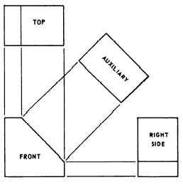
Look directly at the front view of figure 3-13.
Notice the inclined surface. Now look at the right side
and top views. The inclined surface appears
foreshortened, not its true shape or size. In this case,
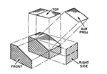
the draftsman will use an auxiliary view to show the
true shape and size of the inclined face of the object.
It is drawn by looking perpendicular to the inclined
surface. Figure 3-14 shows the principle of the
auxiliary view.
Look back to figure 3-10, which shows an immov-
able object being viewed from the front, top, and side.
Find the three orthographic views, and compare them
Figure 3-13.—Auxiliary view arrangement.
Figure 3-12.—The perspective.
Figure 3-14.—Auxiliary projection principle.
3-5


